I wonder if i trained a large language model on the contents of this blog and used it to generate new posts, whether it would generate interesting enough stuff to at least shame me into creating new posts?
This would require that I actually learn something about this topic at least. Although it probably would also require some hardware that I currently don’t possess.
It was twenty years ago today that I first posted something to my brainwagon blog. While I have sort of fallen out of the habit of posting to this site, it still remains as an testament to my inability to concentrate on a single topic for more than a couple of days. I keep thinking that I should stop posting to Quora, and should instead refocus my efforts to the sorts of things that I used to routinely blog about, but I haven’t quite gotten back into it. It’s not that I have stopped doing nerdy things. I still am doing woodworking. I want to get back to rebuilding my first telescope. And I’ve spent more than a little time building a “homelab” computing setup. But I haven’t mustered the degree of concentration and the sense of community that used to drive me to blather on inside these pages.
Hey gang, I know it’s been quite some time (since last May apparently) since I posted anything new on the blog. It is not that I haven’t been doing projects. The continuation of the COVID-19 pandemic generally means that I’ve had a lot of extra time, and have been tinkering with a bunch of different projects and learning new skills. I just haven’t felt much like writing them up.
But I realize that I miss some of the interactions that writing a blog brought about, so maybe it would be good to write up a detail or two of some of the projects. We’ll see how successful I am.
Today’s projects will center around microcontrollers based around the ESP8266 (notably the WEMOS D1 Mini are some of my favorites) and the Tasmota firmware.
The WEMOS D1 Mini
If you haven’t encountered the ESP8266 microprocessor before, you can use google, but the basic idea is that it’s a small controller which is both very cheap and allows access to WiFi. They come on various boards, but one of the most popular is a small board which is called the Wemos D1 Mini. I’ve used them in a few of my own projects before, including an internet enabled clock and my old half life clock that I built a while ago. Did I mention they were cheap? You can get five of them for $17 or so from Amazon. That’s even cheaper than clone Arduino Nanos, and did I mention they have Wifi? They have Wifi.
Programming with platformio
The Arduino has been popular in part because it has a friendly set of libraries and an IDE that can be used to program them. It turns out that with a little work, you can pretend that the ESP8266 is just a different type of Arduino, and all your skills could transfer into programming these things.
But I prefer to http://platformio.org which is a more command line driven approach. You still program the same way, but you can use your favorite editor (vi for me) to create the source code, and can compile and install using simple command line tools. It also provides convenient access to a lot of different libraries.
Using platformio I had created a bunch of different projects over the years. For instance, I created this clock to download ISS data from the Internet and provide a small display with the location of the ISS.
I’d also made clocks, and a variety of adhoc sensors like https://brainwagon.org/2018/12/09/how-not-to-code-an-simple-iot-sensor-and-a-new-task-list/comment-page-1/. But each time I wanted to do a fairly simple sensor project, it kind of meant an afternoon of programming. Granted, not particularly difficult programming, but neither was it trivial. I kind of wish there would be a simpler way I could attach a simple sensor to the esp8266, and get it routed to a server for logging, graphing or data analysis.
Tasmota Firmware
A couple of weeks ago, I was doing my usual browsing/tinkering, and encountered something which I hadn’t considered before. https://github.com/arendst/Tasmota is a firmware that can be downloaded to ESP8266 (and more modern ESP32 boards) that are often used for IOT peripherals. I had used it before when I experimented with SONOFF switches. Here’s the product page. These are cool because using them you can create a switch which doesn’t rely on any cloud architecture to run: you can control it with simple MQTT or HTTP messages. But I had missed a couple of things that I hadn’t realized before.
First of all, you can install the Tasmota firmware very easily on the WEMOS D1 Mini. The easiest way is to bring up the Tasmota Web Installer on chrome, and select any one of a bunch of precompiled versions of the Tasmota firmware, each with different sets of potential sensors or capabilities. You then simply add your sensors to the board, fire it up and configure it’s wifi and MQTT settings, and you have a capable little sensor.
The first of the many applications that I saw was actually something I was interested in. Ikea sells an air particle sensor box which costs just $13.00. This is considerably cheaper than some of the other sensors I’d experimented with before. But out of the box, it just lights an LED bar to indicate the air quality (green for low, yellow and red for higher levels). By itself, that sensor is not particularly useful. I want to have quantitative data, and to be able to log the data to an MQTT server.
Luckily, someone had done the heavy lifting before me.
A quick trip to Ikea purchased a pair of these little guys. This afternoon, I opened one of them up and did the necessary modifications to add a WEMOS D1 Mini with the appropriate firmware.
I could have added another sensor directly in case (there is plenty of space) but I chose to simply create a second WEMOS that used a SHT30 temperature/humidity sensor that I had a little carrier board for. Both send their data to an MQTT server.
Node Red front end
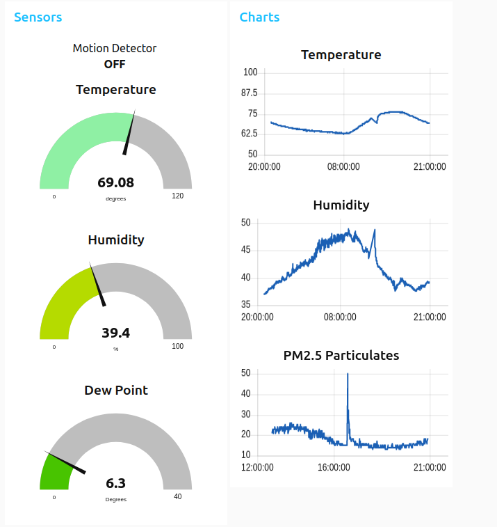
I could have written a little Python script to slurp up data from the MQTT server and produce graphs and the like, but there is an interesting alternative: Node Red. It’s a sort of graphical programming system that allows you to wire up data sources (like MQTT inputs), process them in various ways, and send them to various other outputs. It is also a convenient front end for creating UI elements that respond. After an hour or so of tinkering, I had the following:
Node Red UI elements
Not too shabby. I experimented with similar things before, and also had the data injected into an InfluxDB database, which provides for linger term storage. I’ll probably work that up again.
A couple of years ago, I also did similar data logging using the INA219 voltage/current sensors on a small solar power setup that I created. At that time, I used custom firmware but I now believe that I could do the entire project without any of that programming. I could simply make a couple of small modules that run Tasmota, and do all the data logging with MQTT and Node Red.
I also discovered that the Tasmota firmware also can serve as a controller for a display device. I had an 8 digit 7 segment display controlled by a MAX7219 chip, which is one of the potential displays that the Tasmota firmware knows about (it also nows about a variety of E-ink and TFT displays). You can send commands to the board using HTTP or MQTT to tell it to send information to the display. In a few minutes, I had it displaying the time, essentially making a small internet clock. That seems pretty cool. I ordered some small OLED displays that I can do more experiments with. I’ll probably need to compile a custom version of firmware to use both the sensors I want and the displays, but it seems like an interesting thing to play around with.
Future tinkering
It’s a fun thing to play with. Inexpensive sensors and displays, wired into your own servers, with little-to-no programming. I like it, and will be looking for other possible projects to make use of my new knowledge.
Sigh. The new version of WordPress is doing stupid things with images. I’ll fix them later.
Okay, so roughly a month ago, I said that I was interested in rebooting this blog, and then once again I lapsed into silence. It’s tough to make something a new habit, even if it is something that you wish to do. But it’s not because I’ve had a lack of new things that I’ve been working on: it’s simply that I’m out of practice in terms off writing about them. Rather than try to frame each of these different things into a consistent, well framed narrative, I am simply going to dump out some of the things that I’ve been working on.
I’ve been interested in writing emulators for old computers for quite some time. In the past I’ve written an emulator for the DEC PDP-1 so I could run SpaceWar!, one of the very first video games. A couple of years ago I wrote an emulator for the 8080 microprocessor so I could make an emulator for the original Space Invaders games. It worked rather well. While goofing around a few weeks ago, I tried to recompile it, but had some difficulties which I eventually ironed out. I also relearned a small amount of the subtleties of that hardware which I had forgotten. Nifty. But it also got me back into being interested in writing another emulator.
I had already been doing some research into the old Atari arcade game Battlezone. I had long wished to actually understand more about how this game managed to achieve the 3D graphics which were quite revolutionary for its time. I had also considered trying to figure out how to extract the vectors that it draws, perhaps with an eye to creating a bit o hanging wall art using EL wire and the vector shapes. Luckily, a bit o work on the internet lead me to the vector ROMs and how the backdrops were encoded. This, combined with some very simple (and very slow) vector rasterization code I wrote lead to me extracting some very cool outlines directly from the arcade roms.
That was fun. I briefly considered writing a full emulator for BattleZone, but it seemed difficult because while the main processor for the machine was my old familiar pal, the 6502, it also included a custom processor that was designed to handle the math necessary to render the tanks in 3D.
So instead I embarked upon creating an emulator for the Atari game Asteroids. It too had a 6502. I started trying to write my own emulator. It’s pretty straightforward to do a half-assed job of this, and I got about 60% of the opcodes implemented before I got grumpy, and decided to cheat by using http://a rather nice little 6502 emulator core which was placed in the public domain. Over the next several days, I managed to get most of the emulator cobbled together while watching Psych reruns. It started out pretty rough. In particular, deciphering the abstract functioning of the vector generator took me a while to sort out.
But I eventually got it sorted out. Note: the 6502 emulator above doesn’t have a proper implementation of BCD mode in the 6502, which makes the scoring incorrect until you sort it out. In the end though, I got it working.
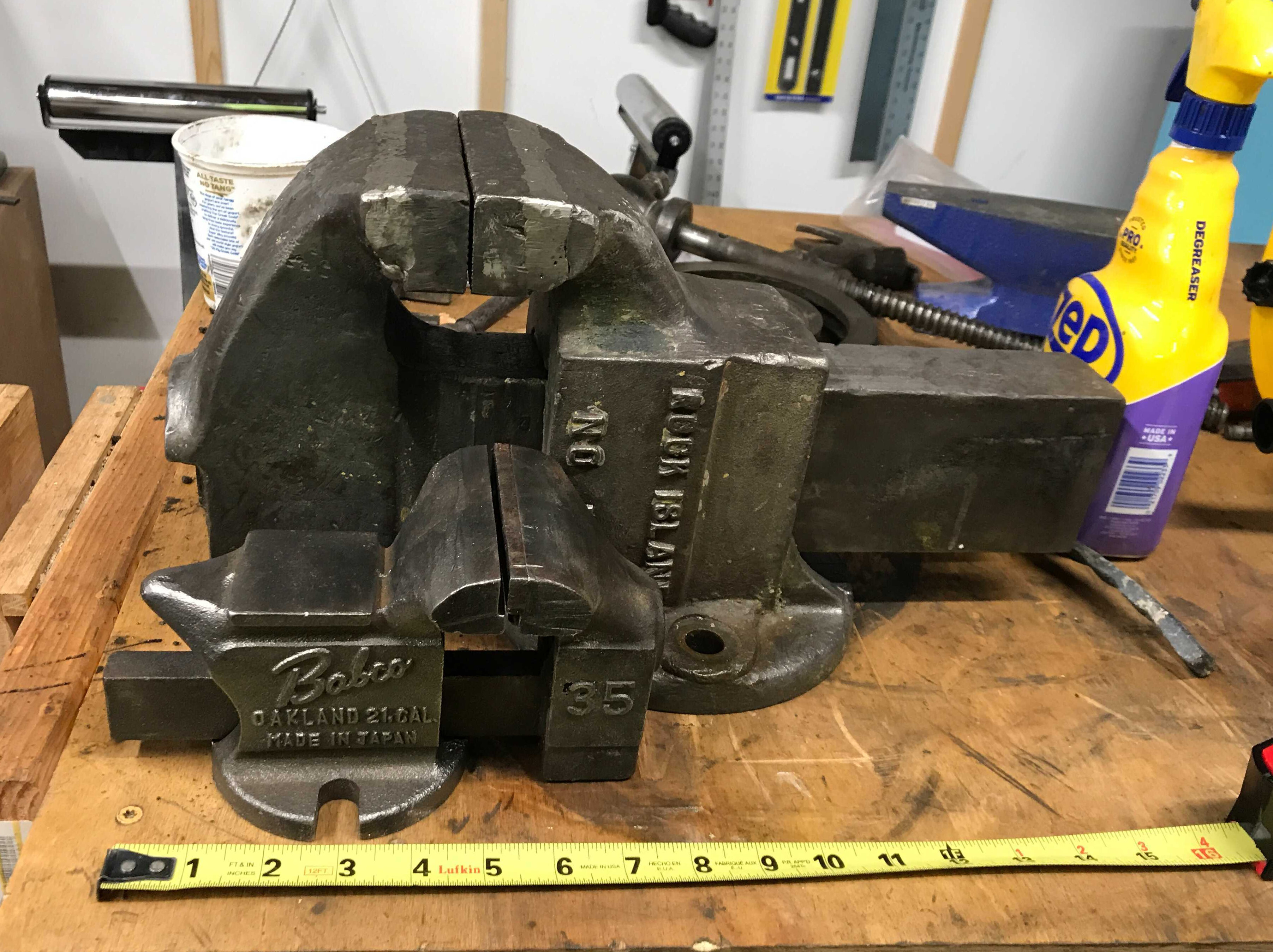
In other news, I went to an estate sale and got a couple of other goodies, including an antique PS&W draw knife, an old Vlchek auto wrench, and a very large (75 pound) Rock Island No, 574 vice.
I cleaned up the draw knife with some 320 sandpaper and WD-40, and it turned out pretty nice. I soaked the wrench in some vinegar for 18 hours, and then hit it with a wire brush and it turned out well. The vice is a work in progress. I disassembled it all to base components, and in the process got tons of old grease all over my workbench. What a mess. I applied some Citristrip to bring the entire thing down to bare metal, and now the project is stalled while I consider how I’m going to finish the vise. Here is the new one with a smaller Babco vise for size comparison.
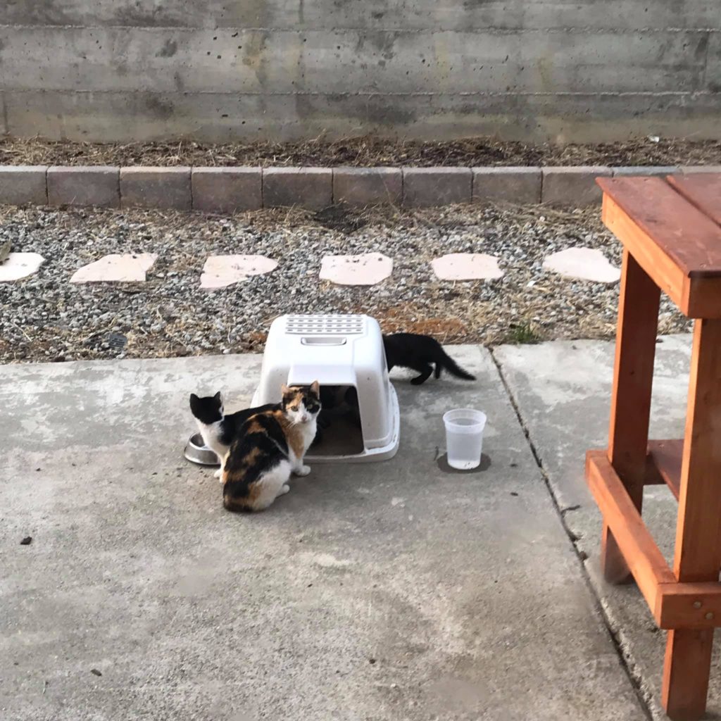
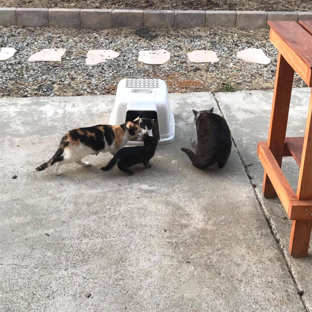
In other news, we’ve been taking care of a couple of feral cats whom we’ve named Whittaker and Patches. Whittaker is a 10 year old male. He got into a fight with something six or eight weeks ago, and we ended up trapping him and taking him to the vet, where he got some antibiotics and was neutered and microchipped. He tested positive for FIV, which makes him not a good candidate for adoption given that I have two indoor cats already, so he’s back out roaming. Patches is a female who was obviously pregnant around the same time. We’ve suspected that Whittaker is the daddy for a long time, given that they occasionally show up together. She was obviously nursing for some time, but we hadn’t seen the babies. Until yesterday.
Patches and Whittaker showed up with five kittens, three of them sort of patchy (although with little orange that we see in mom) and the other two inky black solid color. My guess is that they are 8-10 weeks old. We are trying to see if we can lure them all down again at once so we can have them trapped, get mom fixed and maybe see if we can get the babies rehomed before they go full feral.
I’m running out of energy, but a couple of weeks ago, I was experimenting with creating anthotypes. They are a photographic process that uses non-color dyes, usually derived from plants. Of particular interest to me was using the spice turmeric. You can create a solution of a non-color fast yellow dye by dissolving some in alcohol and painting it onto paper. You then can sandwich a “negative” (which is actually a positive) which I created by printing a black and white image onto some clear transparency, and then exposing it in the sun for around 40 minutes. The yellow bleaches out and yields a yellow print which has very low contrast. But you can “develop” this print in a solution of borax and the yellow will turn a darkish brown. The print is still low contrast, and has questionable longevity, but it was a fun afternoon to give this a whirl.
Anyway, Patches is now out back and looking for some food, so I think I’ll give her some and prep for work. I hope you all are having a good week.
Okay all, it’s been a while. If anyone is reading this, then welcome back to the brainwagon blog.
I’ve been blogging off and on for about fifteen years, but in the last year have found that it’s basically been hard to do anything meaningful here. Between the COVID-19 pandemic and the unfortunate illness and passing of my brother, I just haven’t had the mental energy to write about the kinds of things that I enjoy.
But I’m trying to regroup, and you might begin to see new content here. I’ve decided to abandon my pointless endeavors on Quora which have taken a bunch of what little time I had, and have decided to try to refocus that energy (which has become more about repelling bile and rancor than doing anything fun) and to find a new way to express myself in positive ways.
At the moment, I’m reconsidering everything. This blog may actually change form into something else, using some technology other than WordPress. Or, maybe it just be restructured and restyled to inspire me more. I haven’t decided.
If you are someone who has read my stuff in the past, and has suggestions of technology or techniques to stimulate your creative muse and/or organize your creative output and get yourself in the habit of creation, then feel free to mailto:mvandewettering@gmail.com and let me know. Or just to say hi.
Try not to sign me up for spam though.
I feel like I need a fresh start. I hope to find one.
I am a fairly basic guy, with fairly basic graphic design tastes. I haven’t done a great deal to customize the appearance of my blog over the years, but recently I’ve been revisiting what is possible in newer versions of WordPress. This means that I’m tinkering with both the look and the functionality that are available on the blog. I may return to the “brainwagon classic” theming, or I may embark on a process of moving the furniture around in ways that you think is pointless. You are almost certainly right. Complain bitterly in the comments if you think I should have left well enough alone.
A couple of years ago, I decided to try to get into the entire 3D printing “revolution”. I liked the idea of being able to do some actual design of custom parts, and then be able to render them in plastic. I first bought an Anet A8 kit, and then later a Creality CR-10 which served as more of my workhorse.
But to be honest, the reliability of this printer was never above 80% in terms of my being able to design or download an STL, dice it with Cura, and then print it at reasonable quality without error.
The most common failure mode for prints was simply failure to get the first layer down evenly with sufficient adhesion to keep the print in place until completion. For PLA, the best means seemed to be to use a piece of mirror as the build plate, clean it every time I do a print with isopropyl alchohol, and then carefully preheat the plate, and do a good job of bed leveling.
The stock machine doesn’t include any kind of automatic bed leveling. You simply adjust the z limit switches and the corners of the build plate to try to get it even and calibrated, and then have at it.
That actually isn’t that difficult, but it’s kind of a pain, so I invested in some money to get an EZABL kit. This uses a capacitive proximity sensor to sense the bed position. You can then reflash the firmware of the printer to recognize the printer, and have it autoprobe the bed position before each print.
All that works great. In theory.
But over the last couple of months, I started to encounter a new failure mode that I hadn’t seen before. The proximity probe basically works to act like the previous Z limit switch: when the sensor gets to a certain position, it closes a little transistor circuit to ground the probe pins which used to be connected to a microswitch. When the sensor does this, it opens a red led (there is a similar red led on the sensor itself) to let you know that the switch is closed.
That all seems to work perfectly. But the new failure mode was that the firmware running on the board didn’t seem to see that switch closure, and it would run the stepper into the build plate repeatedly. The Z axis drive belt would then slip making an annoying sound which would continue forever, or at least longer than I could stand before switching the printer off and resetting.
Irritating.
It did it a few times, then mysteriously it stopped. I was making prints related to my telescope refurb project, and then suddenly it was back. Annoying. I did some brief testing. The sensor was detecting the position just fine, but it didn’t seem to register as a triggered event.
I finally got fed up, and sat back and thought. “If the cable connecting the sensor to the Z limit switch had a fault, that would be bad. How can I test it?”
Well, you need to disassemble the printer, pull the cable and verify its operation. So I disconnected the printer from its position in the corner of my dining room, carefully cleared my garage workbench so I would have plenty of work, and moved it there for disassembly.
It’s kind of annoying to disassemble the control box. The motherboard is mounted on the underside of the metal control box, with a 12V generic power supply module in the way. I had done it before, but I had forgotten how annoying it was. I eventually got all the parts pulled out, and extracted the cable in question. I set my multimeter into continuity check mode and…
The cable seems fine. Frown. Maybe it was just loose? I could take the half hour or so to reassemble it (annoying, since it feels like the kind of job that could just take a few minutes) but there would be no guarantee that I wouldn’t immediately have to take it apart again. Should I just spend $12 or so and order a new cable pack just to be sure?
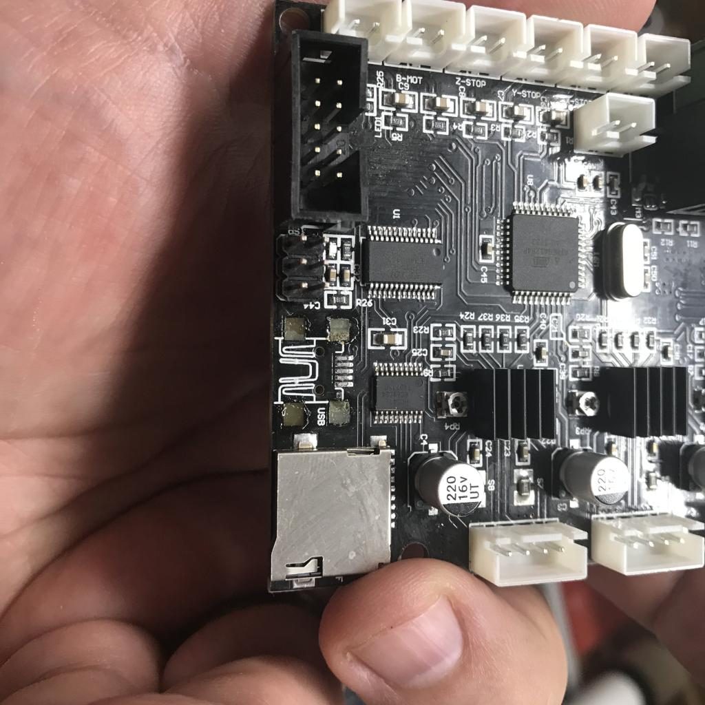
While I had the motherboard out, I decided I should at least take the time to reflash the firmware (there were a couple of changes that I was thinking of making anyway). The motherboard is based upon the same sort of Arduino chipset that everything seems to use, but for some reason (ROM space?) it doesn’t include a boot loader, so needs to be reflashed via a six pin port. It would be easier to do this while the printer was apart.
But then I noticed something bad. The mini USB socket mounted on the board was loose. While examining it… it simply tore loose.
Sigh.
So… I could probably fix this. I could get a new socket, mount it in place with a little CA glue, find a smaller tip for my Hakko soldering station, and replace it. And in fact, I just went ahead and ordered some cheap USB connectors to do that.
But I wonder whether I shouldn’t just chuck this old 8 bit motherboard in the bin and move to something more advanced.
So I took what was a very small and limited project, and expanded it into something that will probably take me a couple of weeks to complete. I ordered a BIGTREETECH SKR 1.4 motherboard. https://www.amazon.com/gp/product/B082YTZJS2/ref=ppx_yo_dt_b_asin_title_o02_s00?ie=UTF8&psc=1 This has a number of interesting added features compared to the previous motherboard. It is based around a 120Mhz 32 ARM processor instead of the 20Mhz 8 bit Atmel chip that runs the old motherboard. It uses the stepper motor modules that are common, rather than having the steppers built into the original model. It can support multiple extruders and dual Z axis motors (nice expansions). It can also talk to the new stepper modules via serial connections, enabling you to set motor currents via software rather than tuning them with screwdrivers. And it also supports limit detection without limit switches: it detects the rise in current as the motor hits the end of motion, and uses that to trigger the limit events.
Oh, and I can compile the firmware and install it just by putting it on an flash card and rebooting the machine. Nice.
But it this does represent a significant set of new challenges as well:
It’s complicated. Lots of new stuff to learn. New software options to reconfigure. New technologies (like no limit switch and serial motor drivers).
It’s not actually mechanically compatible with my existing setup. If I were to try to put it back in the same box, the USB and microsd slots wouldn’t line up. That means I’m committing to building a custom case for it.
It doesn’t actually address the sensor issue that originally started me on this journey in the first place.
But that’s the path I’m on. I think that I’m going to get some 1/4″ Baltic Birch ply and use some of my box building skills that I’ve been practicing and make a simple enclosure to hold the parts, but with plenty of room to make them all easily accessible. I think I’ll also include space for the Raspberry Pi 4 that I use to run Octoprint. I may make this the same size as the base of the printer, so I can actually stack the printer on top and reduce the overall footprint.
I’m trying to look at this as another skill building exercise, which is rather the point of my projects anyway.
If anybody has embarked upon a similar path, drop me a note (twitter is a good place @brainwagon) and let me know if you want to talk me through (or out of?) this line of endeavor.
Part of my recent interest (obsession) with getting my shop equipped for wood working is that I want to return to an activity that I used to do a lot more of: telescope making. In particular, my six and eight inch Dobsonian telescopes that have been relegated to the garage, collecting dust could use some work to make their mount and tube assemblies as nice as the optics. The six inch was the first telescope that I ever did, and I began with my father back when I was only 10 years old. The eight inch was the first telescope that I completed back when I had first begun attending the Chabot telescope maker’s workshop in the early 1990s.
Currently I’m in the “analysis paralysis” mode. This mode is characterized by me sitting with my laptop and some of my reference books, and looking at what others have done and what I could do, and try to plan out an idea about what the design should look like and what it’s capabilities should do.
Here is where my thinking carries me…
I actually lack the patience to really do full on astrophotography, but would like to dabble, and at least be able to do video astronomy. There, the goal isn’t so much to be able to find or track dim fuzzies for long exposures, but merely to keep the telescope smoothly aimed at one of the brighter planets, sun or the moon.
This is actually an easier task than building a full on “GOTO” system. People have been building what are known as “equatorial tracking platforms” for years, and they seem practical and within my skill and tool set. It can be fabricated out of high quality plywood, some strip aluminum and skate bearings, and is not particularly challenging to design. Another good feature of this design is that it is basically a platform which can be added to a conventional Dobsonian design, which means that I can proceed with revamping my old telescope with the assurance that at some later point, I can embark upon this phase with some confidence that it will be useful.
I’m going to start collecting links and information for this project, so that other interested parties can follow along. I’m not certain that it will become a full on “how-to” guide, but I am going to document what my thinking is and log resources that I used along the way, which might be helpful to others.
You would think that with the shelter-in-place orders that we are all under, that I would have had a lot of time and energy to get back to blogging again. I mean for the last eight weeks, I’ve been having to find ways to entertain myself, and in the past blogging has been part of what I would entertain myself. And yet for the better part of the last eight weeks, I’ve basically blogged about nothing.
Which isn’t to say I’ve been doing nothing. Close to nothing, but not actually nothing. My last post was about experiments with AREDN, the Amateur Radio Emergency Digital Network. I’ve still been playing with that, and have got a new Raspberry Pi 4 to add to that network. I’m working toward creating a portable node that will be entirely solar powered. But that’s not today’s project.
I’ve been continuing to tinker with tools. Even in quarantine, I managed to find some tools for sale via Facebook Marketplace, and picked up four rusty planes that I spent a couple of evenings cleaning, de-rusting and sharpening. I have been working on converting a ratty 4×8 sheet of plywood into a rolling stand I can put my Work Sharp sharpening station on.
And, beginning last night, I started working on making a box. At this point, I’d normally insert a picture of the work in progress, but I doubt it would impress any of you. But for now, it will be a box about 12″ long x 5″ x 5″, and is in the style of Japanese toolboxes. If you just search for “Japanese toolbox” on Google, you’ll find hundreds of examples, many quite elaborate and fancy, some very basic. One of the more basic examples with instructions can be found from Make Magazine #34.
It really makes me sad (and faintly insecure) to read comments like this. Because I’ve probably spent eight or ten hours in the last week doing nothng but thinking about boxes. Not just boxes, but this particular style of box.
In a sense, this is just about one of the simplest forms of boxes you can make. There is no fancy joinery like dovetails or finger joints. They are not traditionally made from expensive hardwoods, since they were first of all a box to safely stash their saws and chisels. They were not even typically glued, and were instead held together with nails. If you want to see the basic idea, this video from “lemongrasspicker” on YouTube is a pretty good intro:
If you get to around 4:45 in the video, you’ll see him attach the feet (really just two battens) by nailing them on and then simply bending them over to clinch the bottom to the feet. This is actually also traditional, even though it probably offends our modern sensibilities.
You’ll also note that he manages to get a split in the board as he’s resawing it. Rather than chucking that piece of wood onto the scrap pile and trying again, he simply glues it back together and moves on. One of the things about this design is that it’s not supposed to generate a lot of ridiculous waste. I find that pleasant as well.
Woodworking is actually all about problem solving. What is the order of operations? How am I going to cut this accurately? How can I fix my mistake? How can I hide a mistake I can’t fix? How can I draw inspiration from other designs? How does my choice of material (or just this board) affect the overall design?
Someone who sarcastically says “you built a box, dude” has never built a box, or even given any thought to what it means to be build a box.
So, I had planed and cut some pieces of pine that I had that were around 5″ wide and 27″ long down to roughly 5/8″. I decided to make the overall box 12″ long. It probably won’t be for tools, but might be used to store some small items. I’m mostly doing it just to continue practicing my skills. Last night I glued the two sides to the bottom. Unlike the video above where the sides sit atop the bottom and are nailed in from the bottom. I attached the sides to the side of the bottom and attached it with glue. I also bored several small holes and pinned the bottom in place using bamboo skewers.
I’ve been pondering the rest of the project. The lid on these boxes are moderately clever, and can even be made to lock in place. I’m debating whether I should give that a try. I might make a simple lid, and then later try to do the beveling operations to make the locking wedge.
But in any case, boxes are interesting. In fact, a lot of woodworking is just different techniques for making boxes of different sorts. To dismiss it as trivial likely means that your understanding of the tools and techniques are only the most superficial.
I’ll get some photos of it when its a bit further along.
So, I’ve had a minimal AREDN network running at my house for the past few week or so, and it is working well. To recap where I stand today, I have three different pieces of RF hardware:
a Mikrotik hAP ac lite, which looks like a small router or network switch. This is widely described as a “Swiss army knife”, since it is incredibly versatile. It can itself act as an AREDN node on either 2.4Ghz or 5.8Ghz, but it is even more useful when it is used in combination with a separate RF node. It has four LAN and one WAN port, and works really well as a bridge between the conventional internet and the AREDN network. It can also operate as a conventional wireless access point. Right now in fact, I am connected to both the AREDN network and the Internet through my Mikrotik . Works very well.
a TP-LINK CPE-210, which is a node which is designed to be placed outdoors. The CPE-210 operates on the 2.4Ghz band, and includes an antenna with a 65 degree output. It is designed to be powered over the Ethernet cable using a power injector which comes with the unit. In theory, the Mikrotik can also serve power to POE devices, but I haven’t tested that yet. But I do have the CPE210 plugged into the Mikrotik device. They don’t communicate with each other over wireless, they use DTD (device to device) communication over the Ethernet cable.
a GL.iNet GLUSB150, which is my “satellite” RF node. It’s currently in my garage, attached to an Ubuntu Linux box. It uses the AREDN mesh to talk to the TP-LINK (over a stunning 30 feet or so distance). The Linux box sees the GLUSB150 as an ethernet, and requests an IP address from the GLUSB150. Then, you can easily access services like HTTP and FTP from the attached machine.
Pretty nifty.
Over the last few days, I have begun to think about what it would take to turn this setup into a portable network node. The basic requirements that I had would be:
Make the node solar powered. My experiments with radio powered beacons last year mean that I have a 25w and a 100w solar panel which I could use for the project, as well as solar charge controllers and a 7.2Ah SLA battery (not very big, but affordable).
Include a small Raspberry-Pi like computer to provide additional network services.
I actually was set on using a Raspberry Pi, but as I dug around my box of development boards, I encountered a Beaglebone Black that I had not used in quite some time (when I booted it, I discovered that the Linux it was running bore a date of around 2013). I decided to revamp my knowledge of it, which could be a whole different story. In the end, I did something somewhat out of the normal mainstream: I loaded it with FreeBSD 12.1. I used to be an avid fan of FreeBSD, and found that one benefit was that FreeBSD had a much less bloated userland, and a minimal (but standard) installation didn’t include a ton of things I didn’t need. I used the binary pkg system to load just the few additional bits I wanted, and I was good to go.
I ended up attaching the Beaglebone Black to my Mikrotik as well, mimicking what I think the final portable node would need. And it works great. I created a very basic webpage which was served using the “one line Python webserver” command python3 -m http.server 8081 which puts a webserver on port 8081. I also enabled a simple FTP daemon (not sure why, but hey).
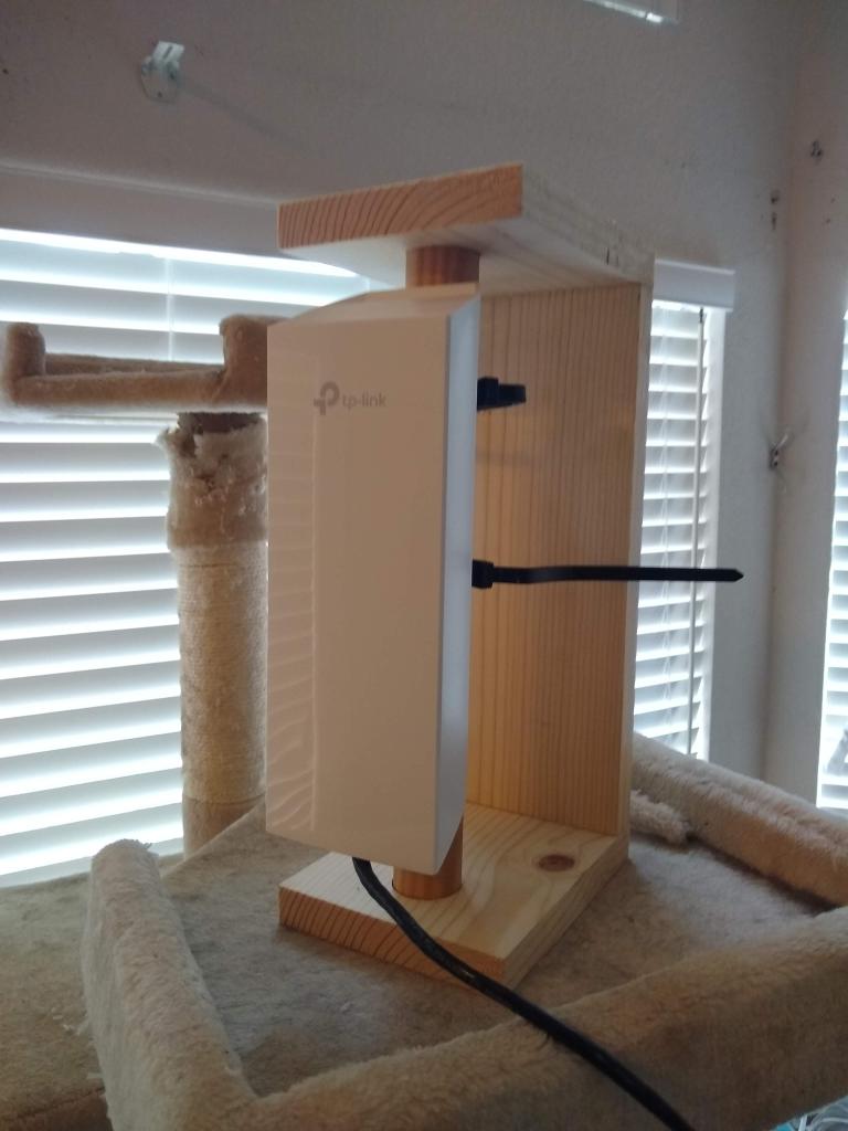
So now I’ve begun to think about how I want to package up the equipment into a tidy and reasonably portable setup. I created a small stand that would make it easier to place and aim the CPE210, and then started to wonder about what voltages I would need and what the power requirements would be.
The TP-LINK on a simple stand
The easiest thing would be if I could power everything from the 12V battery directly, but of course life is seldom that straightforward. To prevent cable losses, POE devices are typically powered by higher voltages, 24 or even 48 volts.
The TP-LINK CPE210 is a bit fussier, requiring power to come over the POE cable, and be between 16V and 27V. This means that we can’t just tap a 12V battery to power it. But we probably could simply use a boost regulator like this one from Banggood (don’t have one handy, but pondering it), use it to provide the input to the DC jack of the Mikrotik, and as they say “Bob’s your uncle.”
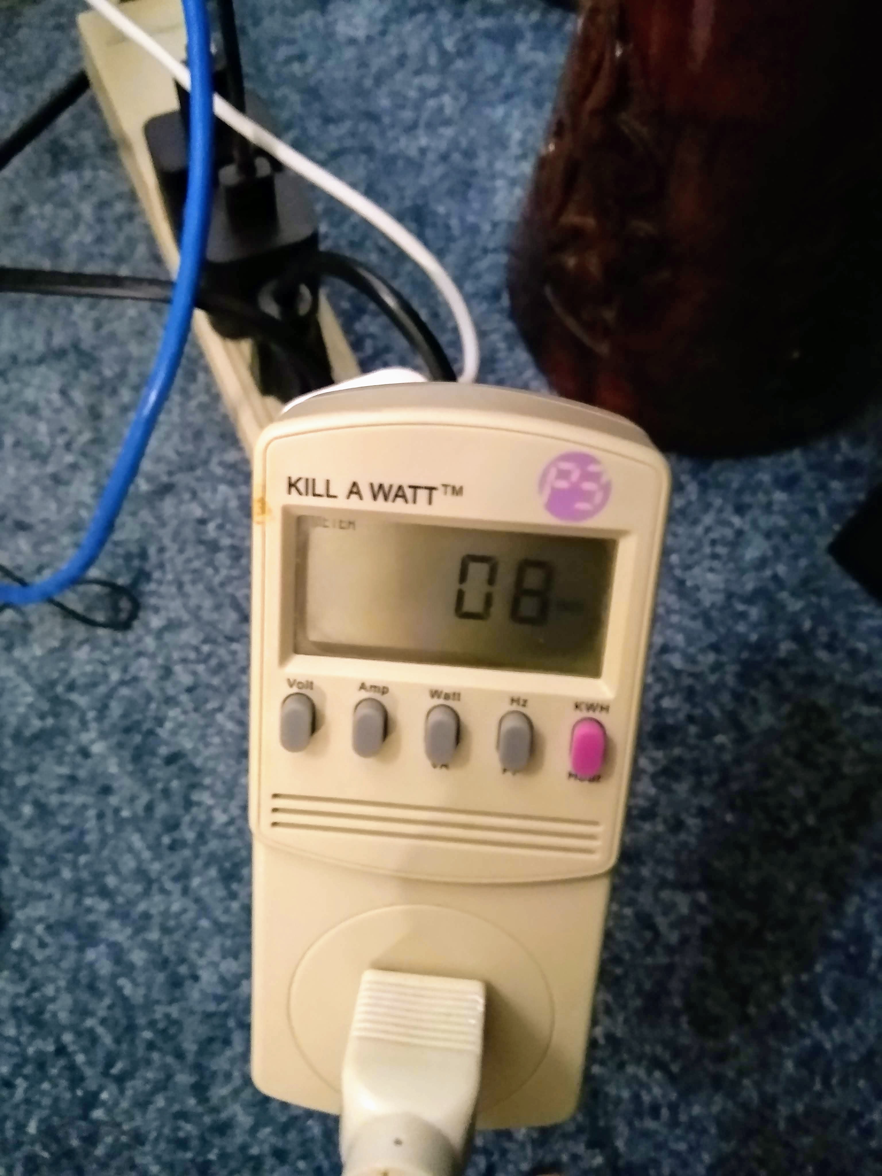
The Beaglebone Black specifies a good 5V, 2A power supply, although says that a 1.2A supply (6W) power supply is supposed to be adequate if you don’t have power hungry “hats” (add on boards) or USB peripherals, which I don’t.
I dug out a little Kill A Watt P3 power meter that I had lying around, and plugged in the three different AC power plugs into a power strip, and monitored the power overnight. In 14 hours, it drew about .11 KWh, which maps down to about 7.85 W, which matches the 8W that it also listed as its instantaneous power reading here.
This was somewhat better than I expected, considering losses from the various AC power plugs as well. But if we assume that value is roughly correct, it means a few things:
In sunny conditions, using my much smaller and more portable 25W solar panel would be entirely reasonable for portable operations. The 100W solar panel would likely be reasonable in all but the cloudiest conditions.
The 7.2Ah cell I have should easily provide 8 hours or more of operating time.
I think the next steps are:
source an appropriate boost converter and manufacture or buy pigtails to get it hooked up on battery power.
I have some small current sensors (INA219) that I used previously in my beacon project. They speak the I2C protocol, which the Beaglebone supports. It should be straightforward to use them to do voltage and current measurements. Ideally, we’d monitor both the current and voltage from the solar panel, as well as measure the input and output power to the boost converter (to measure efficiency).
Start figuring out the physical layout to make a simple, easy to deploy portable node.
So, I have a spare computer out in my shop which I have used to host various small bits of networking. Previously I used it to host reports from my solar powered WSPR beacon. I thought it might be nice to make it available on the AREDN network as well.
This machine uses “conceptron” as its hostname, and because I didn’t have a convenient way to get a cable pulled out there, it connects to my home wireless network via a small TP-LINK USB wireless dongle. I decided to plug the dongle that I was using to provide a link to my AREDN nodes (the GL.iNet GLUSB150) into that node to also make it available on the via the AREDN network. I plugged it in, configured the network, and was easily able to access it via the AREDN network.
But I was no longer able to access the node via the conventional Internet.
The problem boiled down to a simple one: the GLUSB-150 looks like an ethernet device. When its plugged in, it is automatically recognized by my Linux box, and it configures a default path through it. Also, because it is a wired connection, it has a higher metric value than the wireless connection. This means that by default, traffic goes out over the AREDN network, rather than the conventional network.
There is a program that you can use to adjust the metric value a given interface. I lowered the new “Ethernet” interface, and things began to behave as expected.
I still have to figure out how to make sure this happens by default upon reboots.
Addendum: Actually, it doesn’t appear that this works flawlessly. It appears to work from within my home network, but not for links outside. I’ll have to think about it some more.
Okay, minor lesson learned about AREDN. I had tried creating a couple of additional services and reserved a couple of DHCP devices on my node K6HX-GLUSB150, but then decided to move the hardware to a new location and wire it to different hardware. So I did, and then tried to delete those services. On the the local node, the old services that I deleted were gone, but they continued to be listed on the pages of different node as accessible.
Apparently the issue is that while the node itself deletes the reference, there isn’t apparently a means by which the services push out deletion events to other nodes on the network. The only way that these cache entries are deleted is if the node itself disappears from the mesh network for a period of ten minutes. So, I disconnected the node from power, let the cache expire, and voila, it’s all back to normal.
I didn’t have a lot of time to do further experiments with my tiny AREDN network, but I did figure out a few things.
To recap: I currently have three devices which have been flashed with AREDN firmware: a Microtik hAP ac lite (which serves as the indoor hub and wireless access point), a TP-LINK CPE-210 (which serves as a node which I can mount outdoors) and a GL.iNet GLUSB150 (a USB dongle).
I currently have the Mikrotik hardwired via Port #1 to my Google Wifi home network. It will acquire an IP address automatically on my home network. The TP-LINK is attached to the Mikrotik via Port #5. Communications between the TP-LINk and the Mikrotik go over this Device To Device (DTD) link, and not via Wifi. I’ve also configured the Mikrotik to create a wireless access point (with SSID K6HX-AREDN) that any Wifi Enabled device can use to access the AREDN network. One slightly unexpected (but welcome) benefit is that any device that is attached to this access point can not only access the AREDN network, but conventional Internet as well. In fact, I’m typing this post as I’m connected to my Mikrotik, and can access both my nodes and the regular Internet. Cool and convenient!
Freed from the need to use the GLUSB-150 to access the AREDN network from my laptop, I decided to move that dongle out to my garage where I maintain a small server. The GLUSB-150 communicates on the AREDN network by talking to the TP-LINK via RF, which then talks over Ethernet to the Mikrotik, which then tunnels through the conventional Internet to other RF nodes in the San Francisco Wireless Emergency Mesh. Neat!
Previously my garage server was serving up a small webpage that monitored the low power WSPR beacon that I setup. I took that beacon down when the weather turned bad last fall, but it should be possible to make that data available via the AREDN network as well. I experimented a bit with creating new services on my server machine (conceptron) that was linked off K6HX-GLUSB150, but had some difficulty and deleted them. Oddly, some dangling references to them (and legion, my laptop) seems to linger on the node. Not sure what’s going on there.
For anyone reading this from some more distant point in the future, I’m in my fourth week of self-isolation to help halt the spread of the coronavirus. I’m exceptionally lucky: I’ve continued my job from home, working surprisingly effectively with a reasonably fast network connection as we try to put our next movie release in the can.
I haven’t been in a store or a restaurant in about a month. My wife has ventured out with mask and gloves to do some shopping on a couple of occasions, and we’ve gone out for brief walks, but the cabin fever is setting in a bit. I woke up at five o’clock this morning and couldn’t get back to sleep, so it looks like my work day will start early.
At least I have a short commute now, although my consumption of audio books is way down as a result.
Anyway, I’m looking for projects, and one that I selected was to experiment with something that I learned about at Pacficon, the Bay Area ham radio conference that I attended last October.
That something is AREDN, the Amateur Radio Emergency Data Network.
AREDN is a high speed digital wireless mesh network that uses inexpensive hardware to link sites into a dynamically reconfigurable mesh network capable of carrying video and audio data, providing chat and messaging, and generally just any other services you might support and provide on the conventional Internet, but using a completely separate and non-commercial network.
Bob Ross, N7RBP, goes over the basic setup of what it takes.
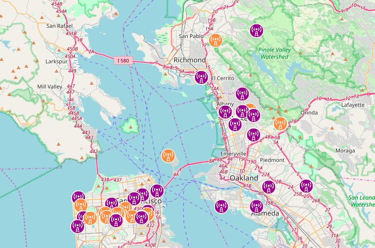
Anyway, I thought it might be fun to try to tinker together something like this. Last October it seemed like there wasn’t a ton of activity in my area, but since then the SFWEM or San Francisco Wireless Emergency Mesh seems to have gained some momentum, and there is considerable activity on both sides of the bay. Going to their website, you can see a map of activity in the Bay Area:
The purple nodes are operating on the 2.4Ghz band, whereas the orange ones are operating on the 5.8 Ghz band. (My own node is currently operating on the 2.4Ghz band, and is the node in the upper right of this map, but I am getting ahead of myself.)
From isolation, I decided to spend a few bucks and get some hardware. I chose 2.4Ghz hardware, for now other reason than it was slightly cheaper. For an external node, I decided to go with a TP-LINK CPE-210 which was about $40 shipped for free from Amazon. It’s basically a router, but with a more waterproof case that is meant to be mounted outdoors. It also has a POE (Power Over Ethernet) injector, which means that to power the node you only need to run a single Ethernet cable to the node. It carries (24v?) power along same cable that your data is carried, which makes installation simpler. I have not yet acquired outdoor-grade ethernet cable, but that’s on my list.
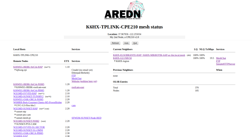
To support the AREDN network, you need new firmware which you can get from their website. My CPE210 turned out to be version 2.8, so I uploaded the v2 firmware from the AREDN site. For that device, it’s straightforward: just use the conventional interface to load new firmware, and you are good to go. The node will act like a conventional access point: you plug your laptop (or better, a switch) into the Ethernet that goes to the node, and it will act as a DHCP server and assign you a network address via Ethernet. You can then access the node via a web interface. Here’s what the mesh status page looks like from that node:
In the column on the left are the list of accessible nodes with their associated services. On the right is a list of the nodes that my node can see directly. There are two nodes you can see, both owned by me. The first is K6HX-GLUSB150, which is actually a GL.iNet microrouter which is a small USB gadget that costs about $30 and plugs into my laptop. It also is flashed to run the AREDN firmware, and looks to my Linux laptop like an ordinary USB Ethernet device. It is currently communicating via wireless to my TP-LINK device.
You can also see K6HX-ELSOBRANTE-HAP, which is a Mikrotik hAP ac lite device. which currently costs about $45 from Amazon. It is also running the AREDN firmware. It’s an interesting device, often called the “Swiss Army knife” of AREDN networking, because it can serve as a bridge between conventional Internet and the AREDN network. In particular, it is one of the simpler ways to provide an Internet “tunnel” to link AREDN networks which don’t have a good RF path to the network.
Like me.
My house is actually in a bit of a valley, without good RF paths to most repeaters. I used the Splat! RF prediction software to see just how bad it is. Assuming I have the ability to place an antenna 50 feet up (doubtful) this is my coverage area. If you’ll compare this to the node map I posted earlier, you can see it’s not got a ton of overlap with existing nodes.
Luckily, Chris, KJ6WEG agreed to give me a tunnel connection that allows my small (three node) network to connect via the Internet to the broader network. This is “cheating” in some sense, but given the current rather poor prospects for a strong link elsewhere, it at least allows me to gain experience.
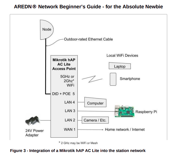
Anyway, my current setup looks more or less like this (from the AREDN beginner’s guide):
In addition to providing a way to tunnel to the Internet, the Mikrotik device can actually create a wireless access point that other devices (such as cell phones) can use to access the network as well. I’ll eventually get a Raspberry Pi configured to hang off it and provide some network services (like webcam, file and HTTP service).
Anyway, I’m having fun from isolation. There is a possibility that the fledgling Pixar amateur radio club may be interested in doing a project (the K6PXR repeater is located in Emeryville, and should have good connectivity across the bay into SF). There is a ton of stuff I still don’t know, and didn’t write up here. Hopefully I’ll learn and write some of it down.
I’ve got an opportunity to potentially loft a small camera module on a high altitude balloon launch next month. I had written some very simple code for an ESP32-CAM module which can be had for about $7 direct from China, or 2 for $10 from Amazon with Prime. The other day I decided to see how long I could expect the battery to last. I grabbed four fresh Alkalines from the Dollar Tree, and measured the voltage for the 4 pack as 6.45V.
I then did something really dumb: I hooked the voltage up to VCC and GND on the module. I should have checked the schematic. The appropriate way to hook it to 5V and GND. Net result, one module no longer responds. I might be able to repair it. Stay tuned for that.
But I then put it on the dashboard of my car and let it sit for the entire workday. After recording something like 1450 images (about 8 hours) the battery voltage had dropped to 5.784V (or about 1.44V per cell) which suggested that they actually had no problem at all. This suggests to me that we probably don’t really need to go to any kind of exotic cell: even at low temperatures, even cheap alkalines will have enough oomph to power the thing for the 4 hours or so that we estimate will fly. I haven’t done the math comparing their relative weights which is another metric we might use in evaluating them.
But in any case, here’s the video, mostly just showing clouds zipping by for about eight hours.
A few other things I learned:
The camera has a fairly narrow field of view. Similar modules are available with fisheye lenses: I ordered one via Amazon, as well as a couple more ESP32-CAM modules to replace the one I killed. I also learned that the AA battery holders I have do not really secure the batteries very well. In the real launch, I should wrap some tape around the modules to keep the batteries from dislodging in flight.
I’m also not sure that the auto-exposure stuff is working entirely correctly. I’ll have to read the datasheet for the camera module a little bit more carefully.